Het bedrijf bob en klussen heeft een bedrijf aangekocht in het buitenland. Aangezien Bob het te drukt heeft in Nederland, heeft jou gevraagd of jij het kan waarnemen in het buitenland en zorg kan dragen dat het netwerk daar gaat werken.
Van de oude CEO van het bedrijf heeft hij nog de volgende taken ontvangen wat er nog aan het netwerk moet gebeuren,
Task 1
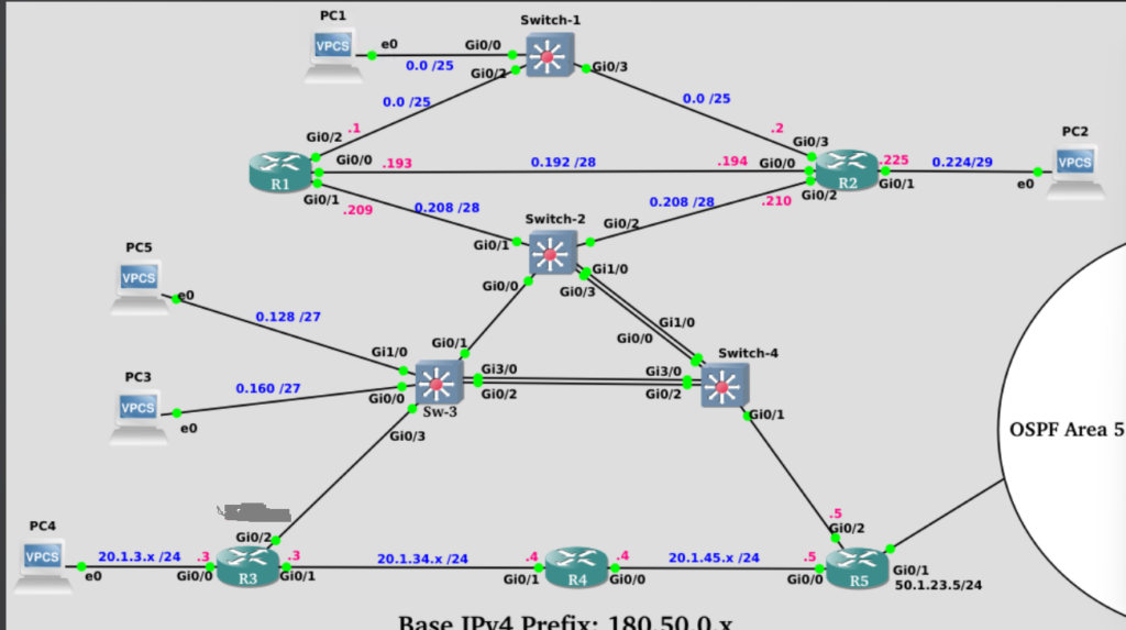
1) Login to Switch-3 and confirm this switch contains VLAN-3 and 4. VLAN-3 should be assigned to interface Eth1/0 and VLAN-4 should be assigned
to interface Eth0/0.
If these VLANs don’t exist or aren’t configured on the access ports specified above, configure it.
2) Configure router R3 as an IOS DHCP Server using the following guidelines:
    This router will need three IPv4 DHCP pools (you may name these pools whatever you wish)

    One DHCP pool will be for allocating addresses to Segment-F using the following criteria:
        subnet = 180.50.0.128 /27
        default-router = 180.50.0.129

    A second DHCP pool will be for allocating addresses to Segment-E using the following criteria:
        subnet = 180.50.0.160 /27
        default-router = 180.50.0.161

    A third DHCP pool will be for allocating an address to PC4 using the following criteria:
        subnet = 20.1.3.0 /24
        default-router = 20.1.3.3
3) Login to PC4 and issue the command, “ip dhcp -d” and verify this PC has obtained an IPv4 address via DHCP from R3.
4) Configure interface Eth0/3 on Switch-3 to operate as an 802.1q VLAN Trunk.
5) Configure router R3 such that it will be able to route for both VLAN-3 and VLAN-4
Assign the first available host address for the relevant subnets to R3’s subinterfaces.
6) Verify that your configuration is correct by doing the following actions:
    Implement the "ip dhcp -d" command on PC5 and PC3 and confirm they've obtained an IPv4 address via DHCP.

    Verify that PC3, PC4 and PC5 can all ping each other.
Task 2
1) Configure OSPFv2 on routers R3, R4 and R5 using the following guidelines:
    OSPF router-IDs should be configured, taking the form of 0.0.0.x where "x" is the router number. So R3 would be 0.0.0.3

    Create a Loopback-1 interface in all three routers and give it the IPv4 address of 77.77.x.1 /24 where "x" is the router number.
        Modify the OSPF network type on these Loopback interfaces so that OSPF advertises the subnet assigned to these loopbacks along with the correct mask of /24.

    R3 and R4 configuration guidelines:
        All OSPF configuration should be done beneath OSPF process-id "1"
        All IPv4 networks on this router should be placed into OSPF Area-0.
        Wildcard masks should match on IPv4 subnet boundaries. For example, if an interface contains a /29 subnet mask the corresponding OSPF wildcard mask would be 0.0.0.7.

    R5 configuration guidelines:
        OSPF on this router should be activated at the interface level.
        Interface Eth0/0 should be placed into OSPF Area-0.
        Interface Eth0/1 should be placed into OSPF Area-51.
        Interface Eth0/2 should be placed into OSPF Area-215.
2) Verify that you completed step-1 by viewing logging into router R4 and answering the following questions:
How many OSPF neighbors does this router have?
What are the Neighbor-IDs and Addresses for each neighbor?
Which router is the OSPF Designated Router on the segment shared between R4 and R5?
In your IPv4 Routing Table do you see any OSPF External routes? If so, how many?
In your IPv4 Routing Table do you see any OSPF Inter-Area routes? If so, how many?
3) Within Switch-4 configure the following:
    A switched virtual interface for VLAN-2 with the IPv4 address of 180.50.0.214/28

    A switched virtual interface for VLAN-5 with the IPv4 address of 20.1.5.4/24

    Any other prerequisite features to allow Switch-4 to route packets between VLAN-2 and VLAN-5.
4) Complete your OSPF configuration on routers R1 and R2 and Switch-4 by placing all of their interfaces (configured with IPv4 addresses) into OSPF Area-215.
5) Issue the command, “ip dhcp -d” on PC1 and PC4 and confirm that OSPF has provided you full end-to-end IPv4 connectivity by pinging between these PCs.
6) On the link shared between R1 and R2 identify which router is the OSPF Designated Router.
Make whatever configuration changes are necessary so that the router that is currently acting as the BDR on this segment becomes the Designated Router. This must be true even when the link between R1 and R2 is up.
7) Confirm that in router R1, when you view your IPv4 Routing Table, you can see entries containing the Loopback networks of R3, R4 and R5 (77.77.x.0/24). Each entry should show a subnet mask of /24 (and not /32) or you didn’t complete Step-1 correctly.